3D Modeling
The dropdown box is helpful when dealing with various modes such as ‘Modeling’ and ‘Animation’.
Views are along the left hand side to get different views of your model.
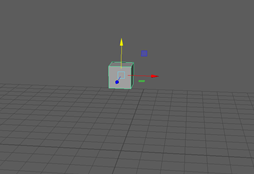
When moving shaped around red = x green = y and blue = z these will never change.
Spaceship Project 11th September 2019
3DTCM1- Understanding the Basic components of a 3D model.
Vertices – A vertex are the points of intersection (where they all meet at a point) between three or more edges. Edges – An edge is any point on the surface of a 3D model where two faces meet. Faces – A face is a 2D image from a 3D shape showing one side of that shape. For example a ‘Box’ will have 6 2D faces of a square. Polygons – Polygons are straight-sided shapes (3 or more sides), defined by three-dimensional points (vertices) and the straight lines that connect them (edges).

In maya I learnt how to use the poly primitives. In my spaceship project I used the cube polygon and continued modeling my spaceship from it this can also be known as ‘box modeling’ as all my other shapes and modeling was all created from 1 cube. I used functions such as the scale, move, rotate and extrude tools to build my spaceship. ( 3DCTM4 ) I have also learnt how to effectively create more detailed designs due to the extrude tool allowing me to make ‘cut’s’ into shapes as seen in my ‘thruster’. This gives my model a more realistic and detailed look to the design and makes the model more interesting to look at.

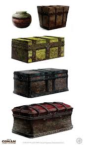
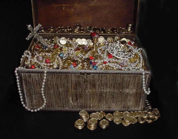
I took inspiration from spaceships online to understand the form and common features of a low polygon spaceship to begin to create my spaceship.

I had a few problems where I would have slices of shapes that wouldn’t delete this is because I was deleting the faces and you can’t delete all the faces on a shape as it has to exist. To fix this I went into object mode and deleted the shape from there this allowed me to fully delete the polygon. I also had a problem when trying to delete an extrusion and then extrude again, to fix this I went to ‘mesh tools’ and used the ‘append to polygon’ to get my missing face back onto my model and this allowed me to then extrude properly again.
I believe that my model is coming along well as my wings and tail of the ship are looking in proportion to one another, the wings don’t look massive compared to the body of my spaceship. I also think that my cock pit of the spaceship is placed effectively and has been manipulated well to ensure that it is realistic and sized well so that it flows well in my model.
UV Wrapping an Unwrapping 18th September 2019
3DTCM1 – Understanding the Basic components of a 3D model. 3DCTM3 – Know how to use a 3D modeling package. 3DCTM4 – Understanding the benefit of good workflows and efficient techniques for creating 3D models.
UV – The letters ‘u’ and ‘v’ denote the axes of the 2D texture because ‘x’ ‘y’ and ‘z’ are already being used to denote the axis of the 3D modeling space. Unwrapping – A UV map is the flat representation of the surface of a 3D model used to easily give textures to your model. UV Shell– A UV shell occurs when you unwrap your model and then break the unwrap into smaller pieces known as a ‘UV shell’. You can think of them as chunks of your unwrapped model. Planar Map – Planar mapping projects UVs onto a mesh through a plane. This projection is best for objects that are relatively flat, or at least are completely visible from one camera angle. Planar mapping typically gives overlapping UV shells.
In UV unwrapping you are basically setting up your foundation that can be used later on to easily give your 3D model textures and allow for clean texturing that can be altered efficiently. the benefit of unwrapping is that it gives you cleaner edges and therefore overall better looking textures.

In Maya I have learnt UV mapping I have learnt how to take my 3D model space ship and convert it into UV unwraps, ( 3DTCM1 ) I did this by using the tool “Workspace: UV Editing” this sets your workspace into UV mode and allows you to see both your 3D model and your 2D UV shells.
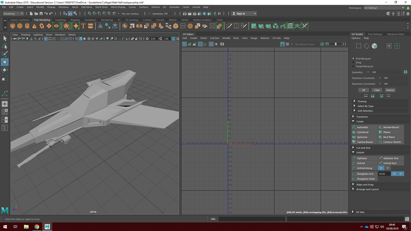
( 3DCTM3 ) UV Editing was then carried out using a couple of tools from the UV Toolkit. These tools included ‘Planar’ – Takes the faces you have selected and converts them into the UV space as a collection of shapes. ‘Unfold’– Takes these collection of shapes and unfolds them flat onto your UV space so that you can texture it properly. ‘Cut’– Takes edges out of your UV shell and allows you to stop stretching and make a more consistent texture. ‘Stitch Together’– Takes edges and places them together in your UV space .
( 3DCTM4 ) In UV Mapping I understand that I should create my own shells this helps my over all UV’s look cleaner and tries to eliminate any problems before they occur due to Maya creating strange shells. I came across some problems when UV editing such as my mesh’s when unfolded collapsed or overlapped this was because of my mesh on my ship being wrong in places and I needed to fix internal faces or point’s where vertices were incorrect. And the overlapping was caused by weird face selects.
Texturing UV Maps 25th September 2019
( 3DCTM2 ) When texturing a texture map can be also called a diffuse albedo or a colour texture map these all sort of mean the same thing until it comes to the theory side of the names however, they all do the same job add colour to your model. To create a colour map you first unwrap your model and then create a texture file by selecting your texture map you had previously created on a external program such as Photoshop. You would then drag and place your textures where you want them relative to your 2D UV Unwrap. This gives them your desired texture you can layer textures giving it more than one element for example on a wooden texture you could add a blood stain on top of the handle of an axe. Textures have a size. Sizes go up in scale 2x per jump for example a small texture file could be 128 the next size is 256. 256 means there are 256 pixels multiplied by 256 pixels along the x and y axis meaning there is 256*256 pixels in your texture size. The bigger the texture size is the more strain the file will place on your game engine.
When texturing I have learnt that I need to ensure my model has a frozen scale and it can mess up unrwaps and this effects the texturing side of it. I created a snapshot photo of my uv wraps and saved this as a PNG this is because it hold transparency and allows us to add interesting effects and layers. The most challenging side of the texturing is using Photoshop I am unfamiliar with the software and because of this it is limiting what I can achieve in the time given for example blending in textures was a thing I didn’t know how to do and because of this I couldn’t get the effect I wanted until it was explained. So far I have given my ship and overall metallic finish with some aspects of decal and elements of design such as a hot backside thruster to give the impression that it has been in use already.
SPACESHIP HAND IN
My spaceship in my opinion is shaped nicely and the process of creating the ship was relatively smooth and simple. I think using polygon primitives to create my spaceship was very beneficial as it stopped my ship from becoming over complicated and difficult to progress with when doing things like unwrapping.
I enjoyed creating different elements of my spaceship using the software package maya. In particular I enjoyed the unwrapping stage of the model the most as it was a challenge at times and got my brain working to solve the best areas to make into a planar. Although there was some restrictions later on due to the complexity of some areas of my ship I tried to do the best I could.
Texturing was hard due to the lack of art theory and some of the shells were not unwrapped correctly. Because of this I did struggle to add complicated aspects of texturing like layering rust or damage to the ship as I couldn’t get the textures to match the ship in a complete way without it looking wrong or too differnt in some areas so I decided to go with a clean look that I will improve after I have modeled and textured more in lessons.
Overall, for my first go at modeling unwrapping and texturing I do belive it has came out better than I thought it was going to because at the beginning I had no idea what I wanted the final piece to look like.
Substance Painter 13th November 2019
( 3DCTM2 )
PBR Materials/ Shaders – Physically Based Rendering (PBR) is a method of shading and rendering that provides a more accurate representation of how light interacts with surfaces.
Metalness Maps – A metalness map takes the metal area ( white in the metalness maps) and it makes the diffuse black. Then it takes what you paint in the diffuse in the metalness areas as the specular power/color control. Everything that is not a metal gets a standard specular power and no color. This means that due to the colour of a map a material or section of a material will look more metallic or shiny if it is painted white, anything black won’t look as metallic and grey is the inbetween.
Roughness Maps – The Roughness input controls how rough or smooth a Material’s surface is. … Roughness is a property that will frequently be mapped on your objects in order to add the most physical variation to the surface.
Emissive Maps – A texture that receives no lighting, so the pixels are shown at full intensity.
Normal Maps – They are a special kind of texture that allow you to add surface detail such as bumps, grooves, and scratches to a model which catch the light as if they are represented by real geometry.
Within substance painter this can be known as a texture set and will help textures look more realistic and finished.

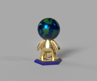
When texturing my model using Fill layers was very beneficial it allowed me to completely texture a part of the model without going over any lines and or making things look messy and unprofessional. I also used a black mask that allowed me to only texture the part of the model I wanted using either polygons or UV shells for specific areas such as the hands. Creating textures the way I wanted them to be was extremely easy due to the Map types such as metalness or roughness that changed how metallic or how rough the material looked. Other useful things like brush alphas and smart materials made this super easy, as instead of creating a gold texture for myself I grabbed one out of the mart materials section that made it look like actual gold and allowed me to concentrate of the finer details like the head.
Most of the challenges I faced were due to the lack of experience with the software such as creating masks. At first it was confusing and hard to implement as I was more comfortable painting over a layer like Photoshop, however after getting used to it, it was much faster and efficient than Photoshop.
My first go at texturing a model is weak and not very refined or creative at all but it did allow me to use the features of the software and let me create something extremely efficiently and quickly. The decent part of my product is the ability to keep a material theme without it, it looks a bit like a POP Funko in the way it looks but has a material of shiny metal it gives it a high quality and expensive finish. In the future I would like to make the overall colour theme more pleasing and create a more overall finished model that has more details within the texture such as dents or scrapes or different color options in terms of the material and quality.
High To Low Polygon Workflow 20th November 2019
( 3DTCM5 ) ( 3DCTM6 )
High to Low Polygon Workflow is a workflow that allows artists to add visual detail to 3D models whilst adhering to the strict polygonal budget that is vital to successfully render in real-time. Two versions of a model – a high-poly model, and a low-poly model – are produced to create a 2D normal map through a process known as ‘baking’, to achieve the illusion of the high resolution detail on the low-resolution model. We would use this to make models look better overall it allows the artist to basically upgrade their model without doing an extremely high poly model.
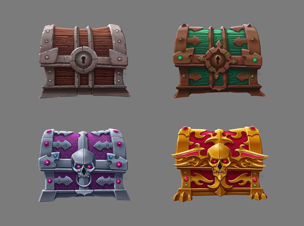
Loot Crate 4th December 2019
Design
Pre-production- is the phase in which ideas are fleshed out and planning of production starts, before the actual animating begins. The general stages of pre-production are character design, storyboarding, and the animatic.
Pre-production is important as it allows work to flow correctly and focused on the task at hand rather than fleshing out into a rabbit whole of cool but irrelevant ideas. In a professional setting this also allows people to work more efficiently and effectively in order to complete their job.
( 3DCTM4 )
Contextual information for modeling
Topology– Topology is the organization, flow and structure of vertices/edges/faces of a 3D model. It is how well you can organize your vertices in your 3D model such that it is efficient, clean and detailed.
Quad– A square or rectangular polygon is referred to as a quad or quadrilateral polygon, and is a four-sided polygon. It has exactly 4 vertices at the corners connected by 4 edges. This is the most desired type of polygon when creating digital models, and many artists like to build their objects using nothing but quads to help make their work more appealing to customers in complex pipelines. Modeling in quads allow the artist to have complete control over their design and allows further manipulation to be simple and easily controlled such as animation using quads.

Tri– A triangular polygon is referred to as a tri or triangle, and is a simple three-sided polygon. It has exactly 3 vertices at its corners and 3 edges connecting those points. This is the smallest configuration required to make a polygonal face.

Ngon– An N-Gon is a polygon with more than four vertices and edges. This kind of polygon. Due to its geometric properties, an N-Gon can always be divided into quads, tris, or a combination of the two; so they are always easy to remove by adding connecting edges between the border vertices. Ngons are sometimes bad as they aren’t always supported when exporting the model making the shapes obsolete.

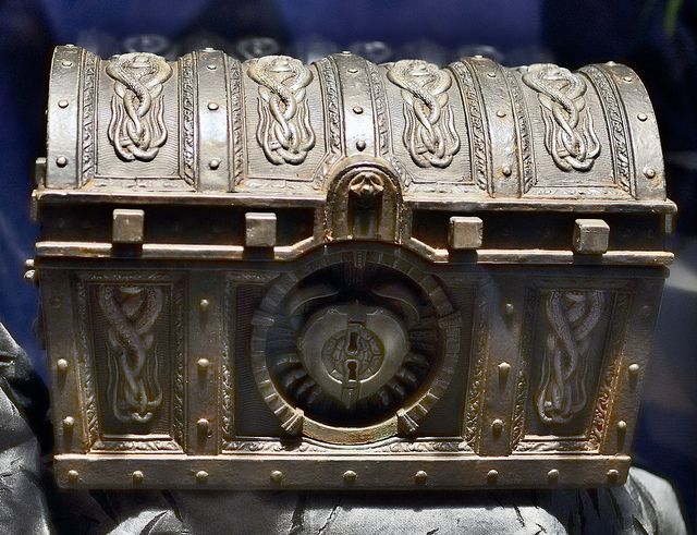
Process of making my Loot Crate
I have learnt about some new 3D modeling terms and techniques such as quads, tri’s, and Ngon’s, mirroring UV’s and modifying topology. Modifying topology is quite a hard process its aim is to make your mesh lines and model look cleaner and neater while trying to avoid tri’s and ngon’s where you can, this is to avoid rendering issues when triangulating your model. Mirroring UV’s can be extremely usefull, the process of cutting shapes into halves or quarters as long as they are symmetrical from both slices of the model. This makes UV editing very simple as there are larger shells and less effort put into unwrapping and texturing as there is less to do. This is beneficial as it allows you to only texture one part of the model, and in most cases while doing this you actually increase the models resolution in most cases making the texture look cleaner and more crisp.
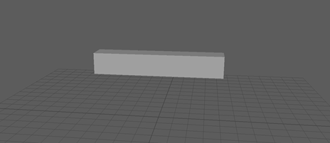
So far I have made a model of a crate that is extremely basic and bland I did this using quads mostly but as my shape gets more complicated I have had to start using tri’s and Ngon’s which I am going to have to fix later when looking at the topology of the crate. Fixing topology and creating quads that actually look the way I want is the most difficult part of the project so far, I do not like the way it looks so far I need to improve the overall aesthetic of my model to make it look more like a crate rather than a strange looking coffin.
Texel Density
Texel density describes the relationship between different textures on different meshes in your 3D scene. Texel density is a formulaic relationship that describes the number of texels (units) that a texture map is divided into.

Texel Density links in with UV optimization by making the resolution of your textures higher or lower depending on the Texel Density of your 3D model. Upscaling models can increase the Texel Density of your mesh. It allows a more consistent scale overall.

In this weeks lesson the focus was high poly modeling, high poly modeling is taking a generally low poly model and adding extra high poly count details to the mesh, meaning details that can be baked easily and would otherwise be difficult to make or incorporate into your mesh otherwise. Example being dent’s, small sections of details like ribbed edges or beveling edges but also large scale but complicated poly counts like a panel created with 0 gap edges to add a sci-fi looking metallic joint.
When making my original low poly model at home there was alot wrong with the topology of my model which made it hard to UV unwrap and created alot of Ngons. This is bad practice and so I restarted the whole crate and started using a more mathematical way of creating my loot crate using edge loops and the connect tool.

So far my work looks alot more confident and easier on the game engine side of the design of my model I am overall much happier with my model as it is going to be alot better in the long run and will look much neater.
